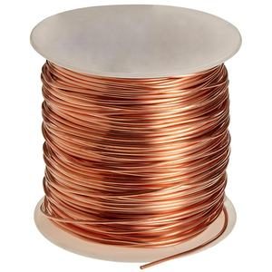

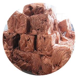
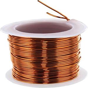
(High Temperature Wire Cable Silicone Wire 10 awg 8awg 6awg 4awg 2awg Silicon Cable Silicone copper wire for car battery Motor)
Parameters of High Temperature Wire Cable Silicone Wire 10 awg 8awg 6awg 4awg 2awg Silicon Cable Silicone copper wire for car battery Motor
The following information is intended to provide guidance on how to use high temperature silicone wire cable in a car battery motor.
## Use High-Temp Web Cables
1. Identify the wires: Before using high-tube silicone cable, you will need to identify all of the wires in your circuit. This includes wires that are commonly used in batteries, such as positive and negative contacts, current limiting resistors, and power transistors. Additionally, make sure to include any other types of wires that may be required, such as ratings, approvals, or certifications.
2. Use a pliers or screwdriver: To access the wires, you will need to use pliers or screwdrivers. Make sure to hold each wire securely while doing so, as attempting to remove one wire from another without proper protection can damage the cable.
3. Place the wires: Once you have identified all of the wires in your circuit, place them carefully onto the silicone cables. Make sure to align them evenly with the rest of the wire, ensuring that they do not overlap. If necessary, use temporary ties or connectors to secure the wires in place.
4. Connect the wires: Once you have placed all of the wires on the silicone cables, connect them together by connecting one wire to each other using a clockwise grip. Make sure that the connections are and that the insulation between the two wires is intact. Be careful when tightening the connections to prevent sudden breaks or loss of insulation.
5. Test the circuit: After connecting the wires together, test the circuit to ensure that it is functioning correctly. You can do this by inserting a piece of electrical tape into one end of the insulation between the two wires, and pulling it out. Verify that there are no traces of any short circuits or insulation breaches.
## Apply Voltage with Silicon Wire Cables
1. Introduce voltage: To apply voltage to the battery, first connect the LED lights and positive contacts to the silicone cables. Make sure to attach them tightly to the positively contact of the LED lights, while leaving the others free.
2. Apply voltage: Start applying voltage to the LED lights and positive contacts using an electrical knife or screwdriver. Be sure to hold the wires firmly in place while applying voltage, as attempting to pull one wire off another without proper protection can damage the cable.
3. Adjust voltage: As the voltage increases, gradually adjust the level of voltage to ensure that the LED lights are working properly. It is important to avoid applying too much voltage at once, as this can cause the bulbs to malfunction.
4. Confirm operation: Once you have applied enough voltage, verify that the LED lights and positive contacts are functioning correctly. You should see that the lights turn on and the positive contacts are responsive to the voltage. Make sure that there are no false positives or false negatives.
## Use Inductive Limiting Resistor
1. Identify the device: To use an inductive limiting resistor in your circuit, locate the resistance within the insulation between the two conductors. The resistance value of the resistor will depend on the type of device and the length of the insulating wire.
2. Choose the resistance: Select a resistive value that corresponds to the current that the device needs to flow through. For example, if the device requires low current flow, you might choose a resistance value that is lower than 1 Ohm. If the device requires high current flow, you might choose a resistance value that is higher than 1 ohm.
3. Prepare the wire: By identifying the resistance, you can prepare the wire for use in the device. Ensure that the wire is straight and clean, and be sure that it is securely fastened to the resistance value.
4. Connect the wire: Once you have prepared the wire, connect it to the inductive limiting resistor. Make sure to slide the resistor into position along the circumference of the insulating wire, making sure that the loop is flat and even.
## Apply with Inductive Limiting Resistor Cables
1. Introduce voltage: To apply voltage to the inductive limiting resistor, first connect the LED lights and positive contacts to the silicone cables. Make sure to attach them tightly to the positively contact of the LED lights, while leaving the others free.
2. Apply voltage: Start applying voltage to the LED lights and positive contacts using an electrical knife or screwdriver. Be sure to hold the wires firmly in place while applying voltage, as attempting to pull one wire off another without proper protection can damage the cable.
3. Adjust voltage: As the voltage increases, gradually adjust the level of voltage to ensure that the LED lights are working properly. It is important to avoid applying too much voltage at once, as this can cause the bulbs to malfunction.
4. Confirm operation: Once you have applied enough voltage, verify that the LED lights and positive contacts are functioning correctly. You should see that the lights turn on and the positive contacts are responsive to the voltage. Make sure that there are no false positives or false negatives.
## Use Copper Wire Cables
1. Identify the wires: Before using copper wire cables, you will need to identify all of the wires in your circuit. This includes wires that are commonly used in batteries, such as positive and negative contacts, current limiting resistors, and power transistors. Additionally, make sure to include any other types of wires that may be required, such as ratings, approvals, or certifications.
2. Use a pliers or screwdriver: To access the wires, you will need to use pliers or screwdriver. Make sure to hold each wire securely while doing so, as attempting to remove one wire from another without proper protection can damage the cable.
3. Place the wires: Once you have identified all of the wires in your circuit, place them carefully onto the copper wires. Make sure to align them evenly with the rest of the wire, ensuring that they do not overlap. If necessary, use temporary ties or connectors to secure the wires in place.
4. Connect the wires: Once you have placed all of the wires on the copper wires, connect them together by connecting one wire to each other using a clockwise grip. Make sure that the connections are and that the insulation between the two wires is intact. Be careful when tightening the connections to prevent sudden breaks or loss of insulation.
5. Test the circuit: After connecting the wires together, test the circuit to ensure that it is functioning correctly. You can do this by inserting a piece of electrical tape into one end of the insulation between the two wires, and pulling it out. Verify that there are no traces of any short circuits or insulation breaches.
## Apply Voltage with Copper Wire Cables
1. Introduce voltage: To apply voltage to the copper wire, first connect the LED lights and positive contacts to the copper wires. Make sure to attach them tightly to the positively contact of the LED lights, while leaving the others free.
2. Apply voltage: Start applying voltage to the LED lights and positive contacts using an electrical knife or screwdriver. Be sure to hold the wires firmly in place while applying voltage, as attempting to pull one wire off another without proper protection can damage the cable.
3. Adjust voltage: As the voltage increases, gradually adjust the level of voltage to ensure that the LED lights are working properly. It is important to avoid applying too much voltage at once, as this can cause the bulbs to malfunction.
4. Confirm operation: Once you have applied enough voltage, verify that the LED lights and positive contacts are functioning correctly. You should see that the lights turn on and the positive contacts are responsive to the voltage. Make sure that there are no false positives or false negatives.
## Use An Inductive Inductor
1. Identify the device: To use an inductive indicator in your circuit, locate the resistance within the insulation between the two conductors. The resistance value of the indicator will depend on the type of device and the length of the insulating wire.
2. Choose the resistance: Select a resistance value that corresponds to the current that the device needs to flow through. For example, if the device requires low current flow, you might choose a resistance value that is lower than 1 Ohm. If the device requires high current flow, you might choose a resistance value that is higher than 1 ohm.
3. Prepare the wire: By identifying the resistance, you can prepare the wire for use in the device. Ensure that the wire is straight and clean, and be sure that it is securely fastened to the resistance value.
4. Connect the wire: Once you have prepared the wire, connect it to the inductive indicator. Make sure to slide the indicator into position along the circumference of the insulating wire, making sure that the loop is flat and even.
## Apply with Inductive Inductor Cables
1. Introduce voltage: To apply voltage to the inductive indicator, first connect the LED lights and positive contacts to the copper wires. Make sure to attach them tightly to the positively contact of the LED lights, while leaving the others free.
2. Apply voltage: Start applying voltage to the LED lights and positive contacts using an electrical knife or screwdriver. Be sure to hold the wires firmly in place while applying voltage, as attempting to pull one wire off another without proper protection can damage the cable.
3. Adjust voltage: As the voltage increases, gradually adjust the level of voltage to ensure that the LED lights are working properly. It is important to avoid applying too much voltage at once, as this can cause the bulbs to malfunction.
4. Confirm operation: Once you have applied enough voltage, verify that the LED lights and positive contacts are functioning correctly. You should see that the lights turn on and the positive contacts are responsive to the voltage. Make sure that there are no false positives or false negatives.
## Use Aluminum Wire C
(High Temperature Wire Cable Silicone Wire 10 awg 8awg 6awg 4awg 2awg Silicon Cable Silicone copper wire for car battery Motor)
Applications of High Temperature Wire Cable Silicone Wire 10 awg 8awg 6awg 4awg 2awg Silicon Cable Silicone copper wire for car battery Motor
-
Electrical Wiring: Used extensively in building wiring for lighting, heating, and power distribution due to its high conductivity and safety.
-
Electronics: Found in PCBs, transformers, motors, and various electronic components where precise signal transmission is crucial.
-
Telecommunications: Copper wires, especially twisted pairs, are used in telephone lines and data transmission cables.
-
Power Transmission: Thicker copper wires are used in power grids for transmitting electricity over long distances.
-
Automotive Industry: Copper wiring is essential in vehicles for the electrical system, including ignition, lighting, and control systems.
Company Profile
Copper Channel is a trusted global metal material supplier & manufacturer with over 12-year-experience in providing super high-quality copper products and relatives products.
The company has a professional technical department and Quality Supervision Department, a well-equipped laboratory, and equipped with advanced testing equipment and after-sales customer service center.
If you are looking for high-quality copper materials and relative products, please feel free to contact us or click on the needed products to send an inquiry.
Payment Methods
L/C, T/T, Western Union, Paypal, Credit Card etc.
Shipment
It could be shipped by sea, by air, or by reveal ASAP as soon as repayment receipt.
FAQs of High Temperature Wire Cable Silicone Wire 10 awg 8awg 6awg 4awg 2awg Silicon Cable Silicone copper wire for car battery Motor
Q: Why is copper used more than other metals for wiring?
A: Copper’s high conductivity, combined with its relatively low cost compared to precious metals like gold or silver, makes it the preferred choice for electrical wiring applications.
Q: Is High Temperature Wire Cable Silicone Wire 10 awg 8awg 6awg 4awg 2awg Silicon Cable Silicone copper wire for car battery Motor insulated?
A: No, not all copper wires are insulated. Bare copper wire is used in grounding applications and where direct contact with other conductive materials is intended.
Q: How do you determine the gauge of a High Temperature Wire Cable Silicone Wire 10 awg 8awg 6awg 4awg 2awg Silicon Cable Silicone copper wire for car battery Motor?
A: The gauge of a High Temperature Wire Cable Silicone Wire 10 awg 8awg 6awg 4awg 2awg Silicon Cable Silicone copper wire for car battery Motor refers to its diameter and is typically measured using the American Wire Gauge (AWG) system, where a lower number indicates a thicker wire.
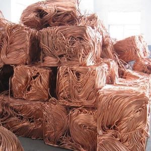
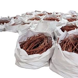
Q: Can High Temperature Wire Cable Silicone Wire 10 awg 8awg 6awg 4awg 2awg Silicon Cable Silicone copper wire for car battery Motor be recycled?
A: Yes, copper is highly recyclable. Old or scrap copper wire can be melted down and reused without losing its properties, making it an environmentally friendly material.
Q: What is the difference between stranded and solid copper wire?
A: Solid copper wire consists of a single, unbroken strand, whereas stranded copper wire is composed of multiple thinner wires twisted together, providing increased flexibility and durability, especially in applications where frequent movement or bending occurs.
(High Temperature Wire Cable Silicone Wire 10 awg 8awg 6awg 4awg 2awg Silicon Cable Silicone copper wire for car battery Motor)